

The initial development
of sensors involves modeling knowledge drawn from many different
discipline s. Inertial sensors design
requires lumped parameter dynamic modeling supported by stress analysis
of beams, thermal analysis of plates, fluid flow analysis and squeeze film
damping. As their size and shapes are altered so does their behavior.
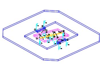
The adjoining figure shows the free body diagram of the inertial
element used in Waddan’s square gyro.
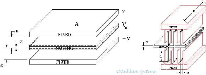
The closed loop devices employ a pickoff (implemented as a set of parallel plates capacitors either with a fixed area or with a fixed gap), a PID controller, and an electrostatic forcer. The level of pick-off signal and forcing action depends upon the nominal gaps and the areas of the capacitor plates. The response of the servo loops, their controlling behavior, stability and bandwidth are analyzed prior to their electrical implementation. The figures below show the fixed area and the fixed gap configurations used as capacitive pickoffs. The displacement sensitivity of these pickoffs is dependent upon the area involved which can be determined from the following limitations:


The tunnel diode pickoff uses the current jumping across a gap between a flat surface and a sharp tip. Obviously, these are suited to sensors where one of the electrodes can be built as a tip with a very small area in close proximity of another flat electrode.
The electrostatic forcing action can be also generated by parallel plate capacitors. Again it is done either using fixed area or fixed gap plates as shown in the above figures.
The residual stresses left after
wafer processing and their affect on sensor response is also
investigated. Waddan Systems employs a dual approach investigation
where experimentation and analysis work in parallel. If a simple
processing experiment can shed some light on a difficult to model
behavior, then that is performed to simplify modeling. The simplified
model becomes a part of the 'What if' integrated development package.
The diaphragm like structures used in pressure sensors and hydrophones
are modeled as thin plates flexing under dynamic pressure waves.
Embedded impedance bridges are fabricated with piezo -electric and/or
piezo-resistive elements to measure the deflection of the diaphragm.
The size, shape and layout of the embedded elements are also determined
by analysis.
The coriolis sensing devices and the gyros are analyzed with detailed
math modeling. This sort of modeling works well with bulk micromachined
or micromolded sensors. Bulk micromachining devices allow bi-polar
approach to implement simple devices like transistors, diodes,
piezo-electric and piezo-resistive elements, diffused capacitors, and
tunnel diodes.
With surface micromachined devices the lumped parameter modeling
does not work well because the inertial elements cannot be made
rigid, because the thickness of structural polysilicon cannot
be increased significantly (the stiffness of the plate increases
with increasing thickness). The flexing and warping of thinner
structures introduces high levels of unmodelable errors in sensor
outputs.


