


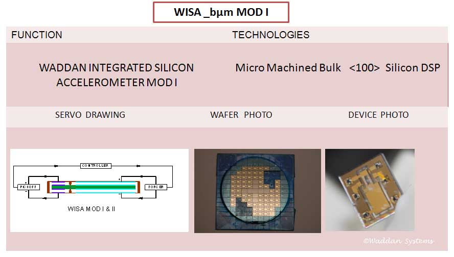
WISA MOD I is our first bulk micromachined device-a navigation grade pendulous accelerometer. Prior accelerometers used to have 100's of components with size factor similar to that of a mechanical wristwatch. WISA MOD I design integrated the functionality of all those components into a single chip.
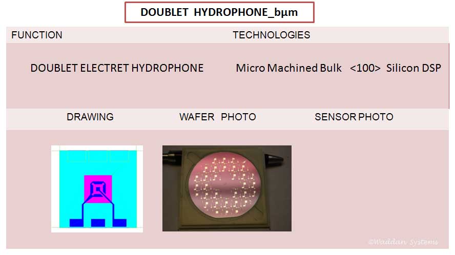
This device is basically a silicon diaphragm with PZT films coated on both on top and bottom surfaces-essentially two hydrophones placed back-to-back. The signal producing PZT films are fabricated as either a Boron/Zinc Oxide/Aluminum or an Aluminum/Zinc Oxide/Aluminum stack. The silicon diaphragm is produced by bulk micromachining.
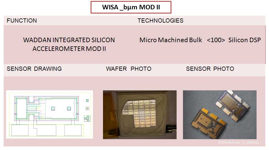
WISA MOD II is also a bulk micromachined device-a navigation grade pendulous accelerometer produced under a crash program to replace WISA MOD I. The MOD I devices had resolution and sensitivity problems caused by a noisy pick-off and electrical contact issues. In MOD II devices the pick-off electrode area is as big as the forcer area of MOD I, and the electrodes can be directly wire bonded. In MOD I they were only accessible through laser drilled holes.
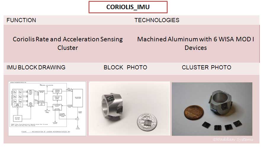
A first use of WISA devices-Inertial Measurement Unit (IMU)-employed three pairs of accelerometers. Devices in each pair were configured to produce equal but opposite coriolis acceleration when subjected to an angular rate input. Summing their outputs yields the linear acceleration, and differencing yields the angular rate.
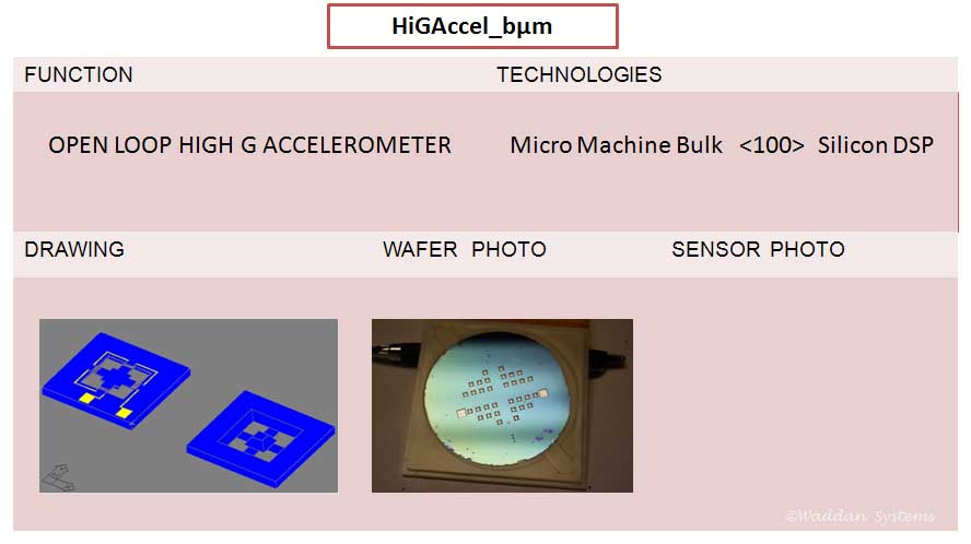
Device designed to measure very high G shock loads such as those produced during a drop from building on a concrete surface, or during a close proximity explosion, or gun launch. It can measure up to 10,000 Gs with a resolution of +/- 1 G.
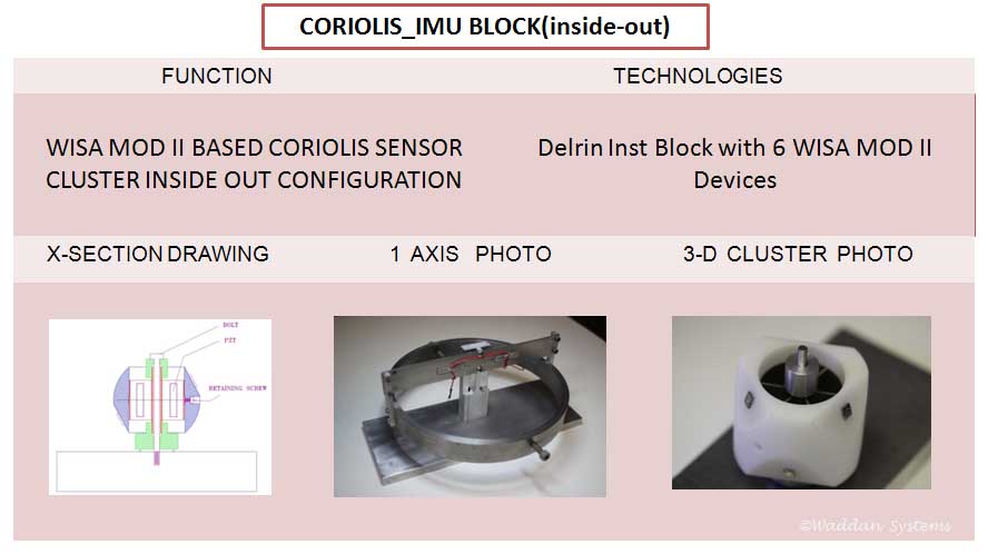
It is an inside-out IMU block configuration where the axial hub stays fixed supporting a dither motor oscillating at 100 Hz. The three accelerometers are mounted on orthogonal (cube) or non-orthogonal (tetrahedron) surfaces machined on a cylinder or sphere (Delrin). A single axis proof-of-concept hardware is shown in the middle photo. This IMU consists of several components assembled together by skilled technicians.
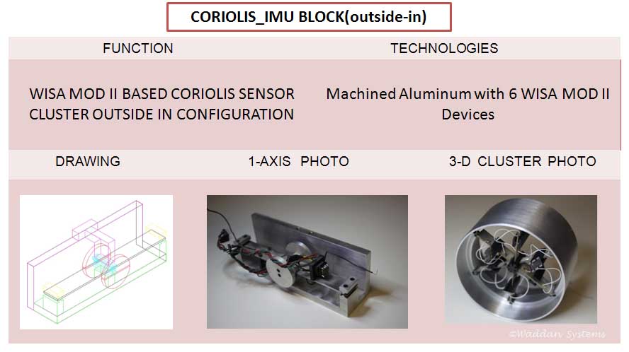
It is an outside-in IMU configuration where the rim of the structure is stays fixed while the axial hub supports an inertial mass. The drive consists of six simply supported flat beams. Each beam is a thin foil sandwiched between PZT crystals. The beams supporting the inertial mass are tuned to resonate at their fundamental bending mode at at 100 Hz. The mid points of maximum deflection support WISA MOD II devices-mounted in such a way that their input axes are orthogonal. A single axis proof-of-concept hardware is shown in the middle photo. This IMU also consists of several components assembled together by skilled technicians.
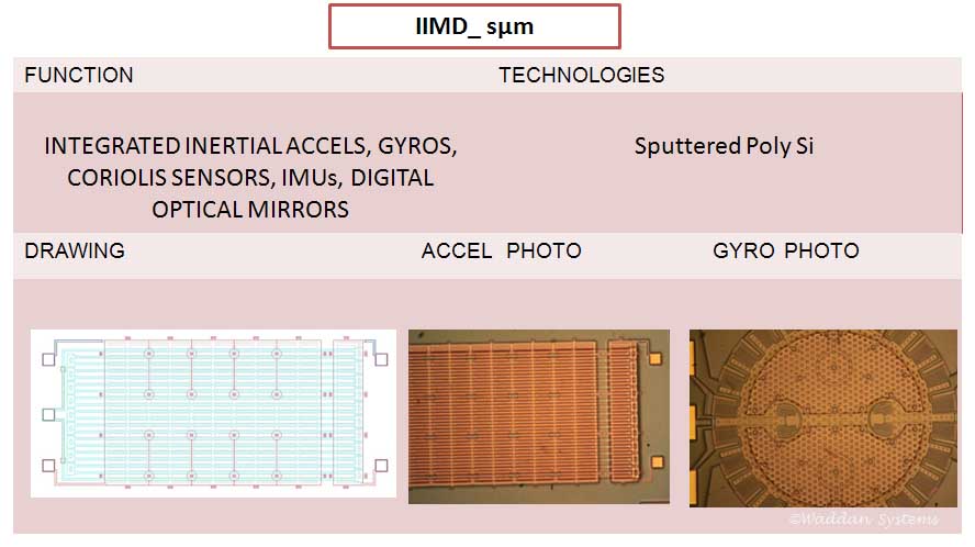
A three layered sputtered poly-silicon surface micromachining approach was used to make these devices. The actual inertial device was etched in the middle layer, while the top and bottom layers served as supporting structures. The devices built included accelerometers (analog and digital), rotary gyros, coriolis devices, 3 axis IMUs called IIMD, gimbaled mirrors, curvature controlled mirrors, optical switches etc.
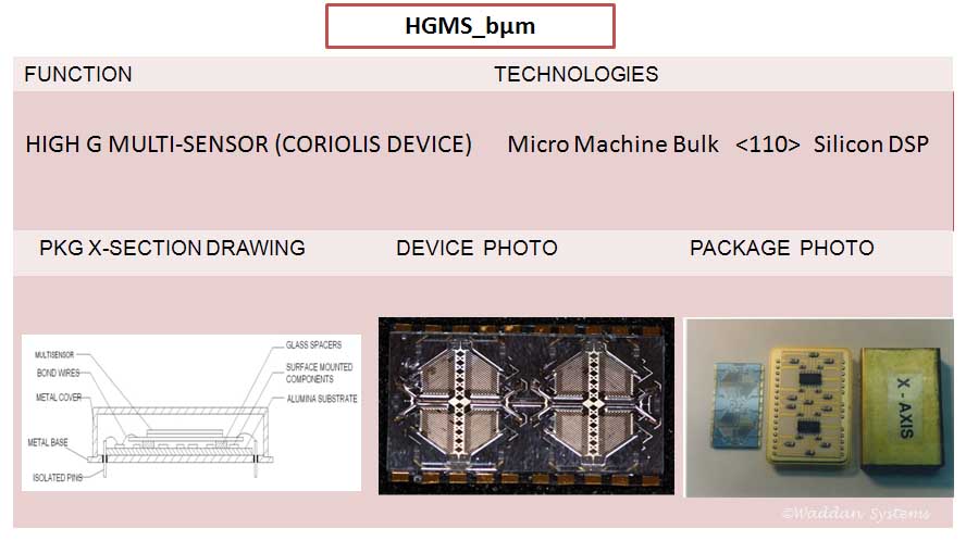
This is the next step in the evolution of coriolis type IMUs. A pair of accelerometers and their dithering structure are all made together in a single device. The device employs three servo loops-one for controlling the dither amplitude and frequency, and other two for closing the loop around accelerometer proof mass. The device is designed to be caged under high G inputs. Three of these devices when packaged orthogonally yiled an IMU.
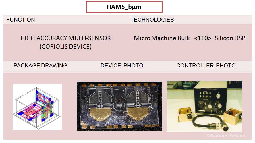
This is the high accuracy counterpart of HGMS. The accelerometer input axis is perpendicular to the device. The caging G-levels are low, but the device control surfaces are much larger than those of HGMS. It has a better resolution but a lower shock G sustaining capability.
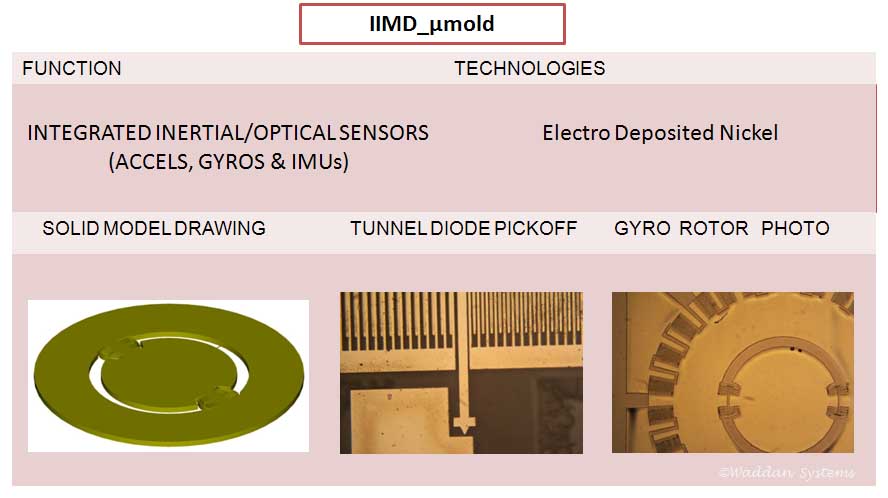
The middle sensing layer in surface micromachined devices is thin (thickness around 2 microns), and thus, are susceptible to warping over temperature variations. The sensing in these devices is electrodeposited nickel with thickness as high as 100 microns (practically no warping over temperature). Devices made include accelerometers, gyros, IIMDs, waveguide devices employing phase modulation, polarization, multi-mode splitting etc.
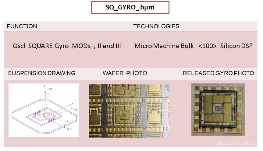
A silicon gyro was developed on the same lines as a classic iron wheel gyro. The iron wheel gyro uses a sensing element with a constant angular momentum, but the silicon gyro has a sensing element with a sinusoidal angular momentum. Its input axis is normal to the device plane. With an angular rate input, the device produces a sinusoidal output that gets demodulated. This gyro requires only two servo loops, and it is a pure angular rate sensing device-unlike coriolis devices which require three servo loops and where the angular rate measurement is embedded in the acceleration measurements.
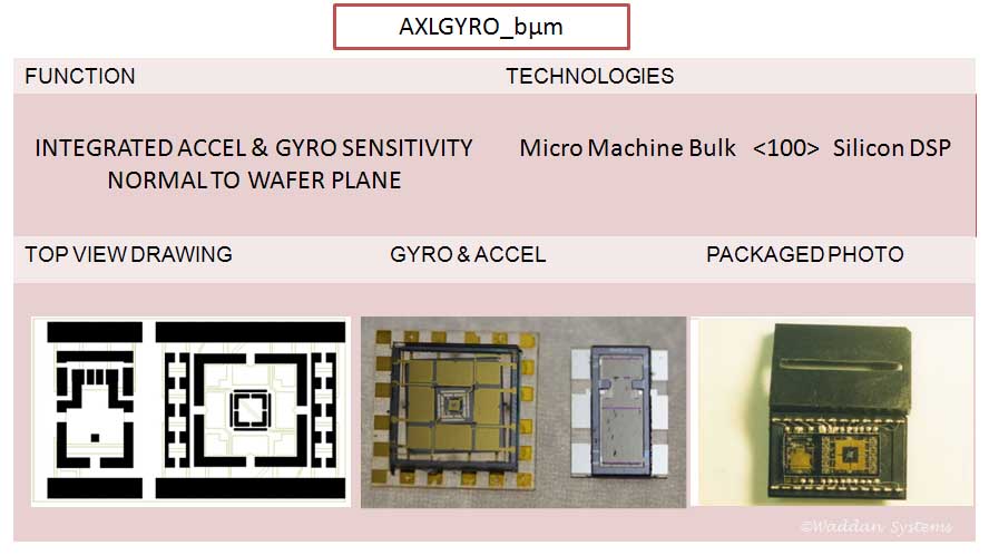
This device was specifically designed for IMUs, which in general are made with three sets of orthogonally mounted gyros and accelerometers. In this device a gyro (like the square gyro) and an accelerometer (like WISA) are fabricated together, thus, an IMU can be built using only three such devices.
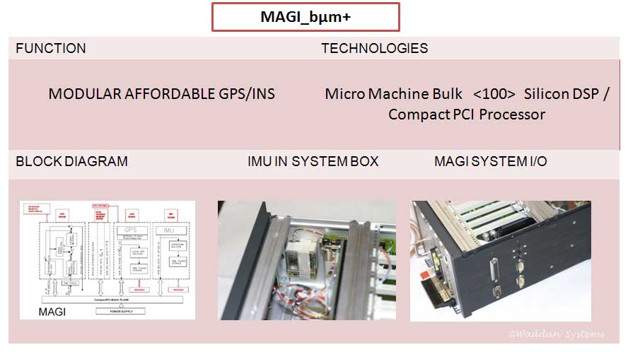
This system combines a commercial GPS unit with an inertial measurement unit. The entire system is modular and uses the compact PCI platform. It has six different modules which can be upgraded individually without affecting the overall size and shape. It has a processor module, a GPS module, an INS module, an I/O interface module, a solid state drive module, and a power supply; all plugged into a common back plane. Each active module has its own software drivers. The system application and the Kalman filter to integrate the IMU and the GPS used Windows NT OS at the time of delivery. The system can be operated as desktop PC based system, or can hang on network as an Ethernet node. The middle photo shows Waddan's Axlgyro based IMU mounted behind the back plane. The photo on the right hand side shows the complete MAGI.
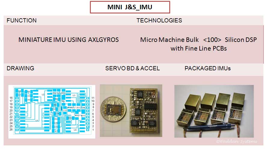
An Axlgyro based miniature IMU measures only 25mmX25mmX50mm. A pair of small boards, shown in the middle photo, contain the sensor and the support electronics for one axis. Three such pairs are packaged orthogonally along with an I/O interface board in the IMU. The right hand side photo shows four of these IMUs
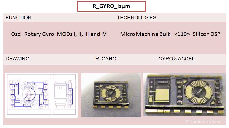
This gyro operates in the same way as the square gyro. The sinusoidal angular momentum axis is normal to device, and its input axis lies in the plane of the device. An accelerometer can also be collocated next to the gyro (as in Axlgyro) as shown in the right hand side photo.
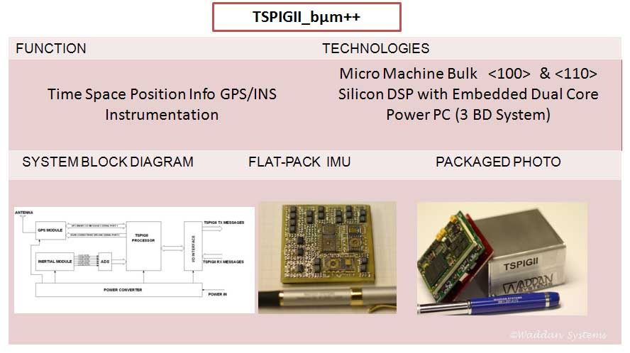
As a natural evolution, an Axlgyro and two rotary gyro modules mounted perpendicular to each other on a PCB form an IMU. A single board IMU, dubbed flat-pack IMU, was built as shown in middle photo above. TSPIGII consists of a flat-pack IMU, a processor board with a dual core power PC, 2 GB RAM, and 16 GB Flash, a third board with a commercial GPS chipset, USB, Ethernet, RS232 and other power conditioning hardware. The TSPIGII systems measures 50mmX50mmX25mm. A customized small footprint embedded Linux is loaded for system processing and interfacing with outside world. Currently it is programmed to provide three nav solutions-GPS alone, INS alone and tightly coupled solution with 50Hz update rate.
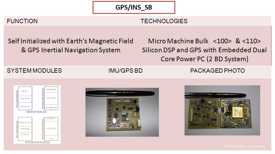
These two boards include higher level of miniaturization than that is incorporated in TSPIGII. In addition to all the features of TSPIGII, it includes a triad of magnetic field sensors and a temperature sensor. The IMU sensors and the GPS chipset are collocated in one board. The second board includes the processor and memory on one side, and the magnetic field sensing triad and the temp sensor are placed on the back side. The GPS provides the initial latitude and longitude. Measurements of Earth's magnetic field and gravity vector yield the orientation of IMU axes wrt to NED coordinates.
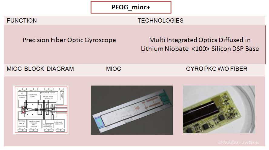
The PFOG is a two component gyroscope-a spool of fiber and an electro-optic hybrid module. The hybrid module includes a multi-integrated optics chip (MIOC) shown in the middle photo. The active optics is fabricated in a Lithium Niobate (or Lithium Tantalate) substrate which is flip-chip bonded on a silicon substrate on strain relieved posts and tapered etched V-grooves. The MIOC is mounted on a PCB with gyro electronics, which in turn gets mounted on one end of the fiber spool.
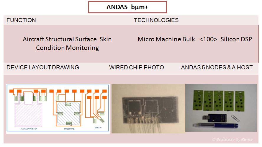
For ANDAS, a very small integrated device was fabricated that included an accelerometer for vibration measurement, a pressure sensor to measure pressure, a thermister to measure the temperature, and a strain gage rosette to measure the surface strain (the drawing shown on the left hand side displays the device layout). A flex PCB with all its components mounted on one side and the device mounted at the bottom edge works as a measurement node. It reads and transmits the measurement data at its mounting location when requested by the host module. The right side photo shows 5 nodal assemblies and a host module.
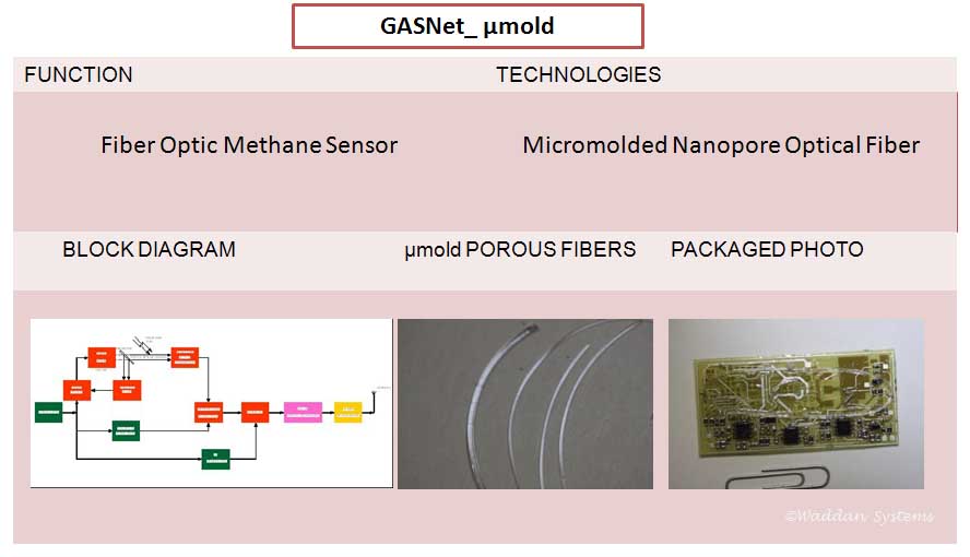
The fibers shown in the middle photo were micromolded in small diameter Teflon tubes. The material employed is a sol-gel, upon curing it forms the optical fiber with nano pores. When the fiber is soaked in methane, depending upon the methane concentration, a 1650 nm laser passing through the fiber is proportionally affected by it. Upon finishing the measurement, the data is transmitted to a host by a wireless transceiver.
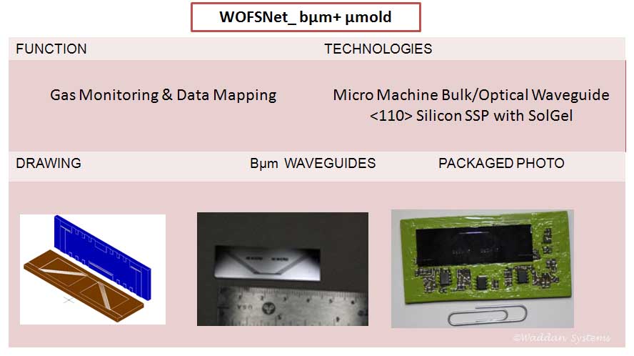
This is basically the same device as the Fiber Optic Methane Sensor described above. Instead of micromolded fibers, it employs a set of parallel precision micromachined waveguids filled with nano-porous sol-gel. When the chip is soaked in methane, depending upon the methane concentration, it affects the 1650nm laser proportionally.
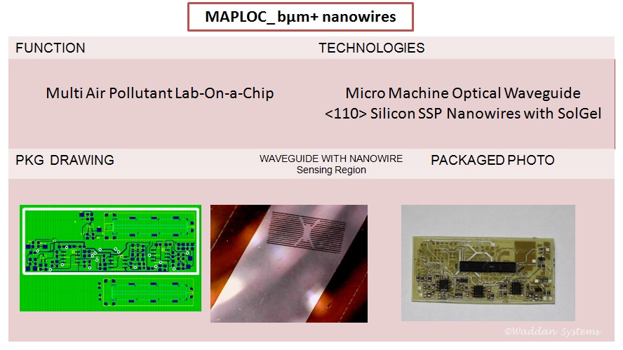
MAPLOC is a MEMS device capable of detecting multiple hazardous air pollutants and volatile organic compounds. The device employs nanowires in combination with a self-assembled layer of organic molecules for gas sensing. Standard processing equipment produces a batch of compact (50mmX20mmX4mm) MAPLOC sensing elements. One of which is assembled using 0603 passive components, a chip antenna, a switch, a wrist watch battery, and 7 analog ICs in the board shown above.