


An IMU is a sub-system of an inertial navigation system (INS)—a key component for autonomous navigation information without any external aid. Prior to the availability faster computing, the inertial instruments used to be mounted on a multi-gimbal stable platform. The sole use of the gimbals was to keep the instruments in a local level plane at any global position. Current INS’ do not use a mechanical gimbal platform, but a virtual coordinate reference platform that exists only in the system computer. It became possible due to faster computational algorithms. That’s why these INS’ are often referred to as strapdown systems (i.e. the instruments are fixed with the vehicle and experience practically the same motion as the vehicle itself). ALL Waddan Systems’ INS’ employ strapdown IMUs.
Generally an IMU consists of a cluster of inertial sensors (accelerometers and gyros) mounted in a triad configuration so that their input axes do not fall in a single plane. Most common configuration is an orthogonal one, where the sensor input axes are perpendicular to each other. Non-orthogonal configurations are also sometimes used, but those with large angles (>120 degree) are mostly avoided.
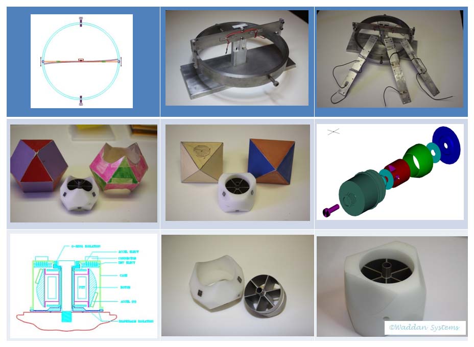
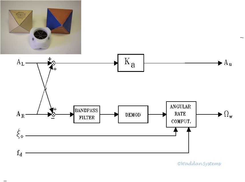
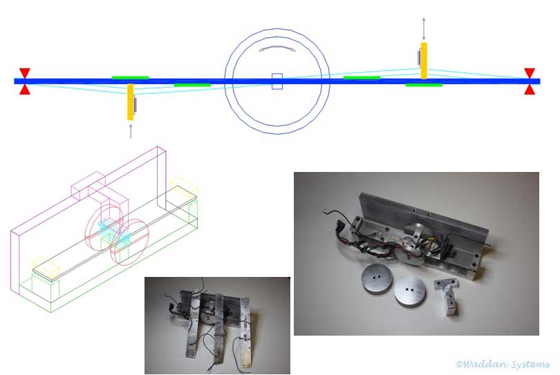
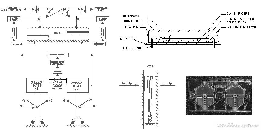
Waddan’s first IMU was made prior to its gyro sensor development. It employs three pairs of WISAs. The devices paired are dithered with equal but opposite side slip velocity. Thus, each device experiences linear as well as coriolis acceleration. Upon summing and differencing the outputs of a matched pair, the linear acceleration and angular rates are separated. The evolution and the principle of operation of the dither block IMU are illustrated in the pictures above. As dictated by the mathematical computations, the input axes of each pair of accelerometers have to be coincident. Moreover, in the 3D block, the three accelerometer-pair axes have to pass through a common origin.
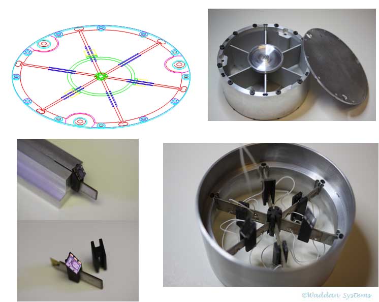 Evolution of the single axis and 3D version of the IMU are shown
in the above pictures. This IMU removes the centrifugal acceleration
noise, which is always present because the imparted side slip velocities
to the accelerometers are not purely linear (directed along a circular arc).
Evolution of the single axis and 3D version of the IMU are shown
in the above pictures. This IMU removes the centrifugal acceleration
noise, which is always present because the imparted side slip velocities
to the accelerometers are not purely linear (directed along a circular arc).
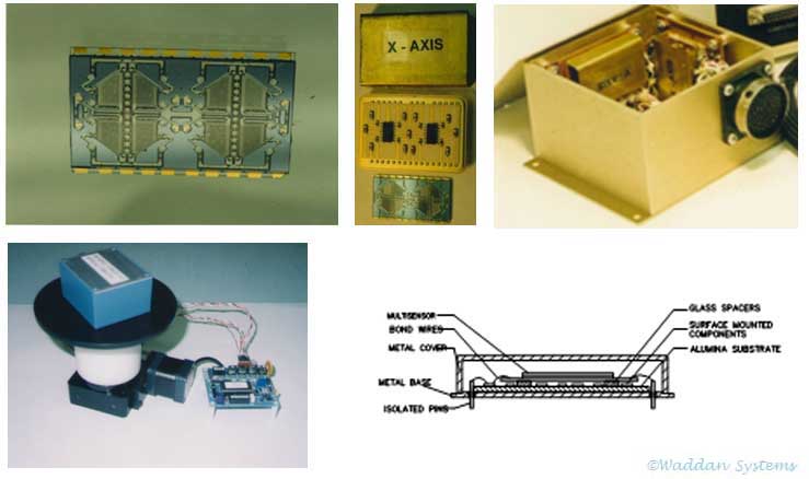
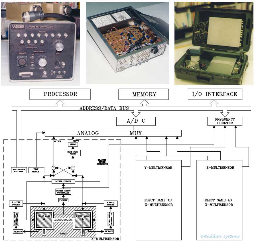
Both the IMUs discussed above were very expensive to build, and required very skilled technicians for assembly. Each accelerometer pair has to be matched closely, and fabrication of the dithering mechanism was very costly. They were not suitable for low cost mass production. The HGMS sensors were designed to remedy this situation. The accelerometers in a pair were built together under identical conditions, and each pair 21 was built with an embedded dithering mechanism. The principle of operation, the machined devices, assembled hybrids, an assembled IMU box, portable rate table, and IMU controller box are shown in the above pictures.
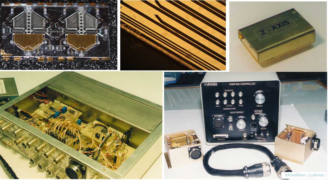
This IMU is built with higher accuracy multi-sensors than that of HGMS. The acceleration and rate input axes are also interchanged. When hard mounted, the HAMS devices cannot survive shock loads greater than 20Gs (a few milli-sec wide). As before, the above pictures show the principle of operation and assembled hardware and a related controller.
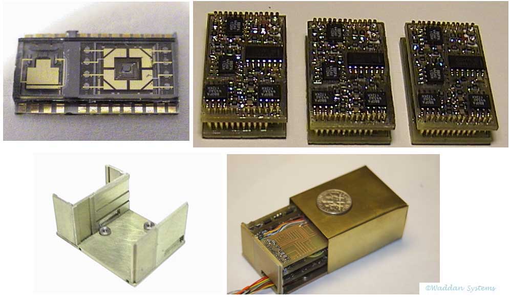
The miniaturization and real cost reduction of the IMU became possible, only after the development of silicon gyro. Then a gyro and an accelerometer were built together—as a device dubbed Axlgyro. The pendulous accelerometer requires a single servo loop for rebalance, and the gyro requires two servo loops—one to maintain the amplitude of the sinusoidal angular momentum, and the other for precession rebalancing. A pair of small boards contain the sensors and all the servo electronics. An anodized aluminum housing with three mounting inserts can house a complete IMU. The IMU requires +12V input, and outputs six analog signals—three acceleration and three rate components along the IMU axes. The above picture shows the single sensor, the electronics boards, the housing and the assembled Match Box IMU.
