


Test Stations can be divided into three main categories. Each has its own specific testing requirements, and thus, the type of electronics required.
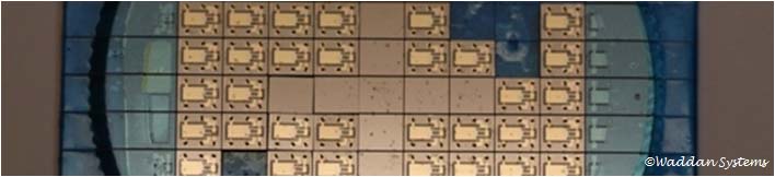
These tests are performed while the wafers are still passing through processing steps. Along with rows and columns of devices, in each wafer some strategic locations are reserved for measurement and testing. For example, to determine the actual etch depth some areas are designed for optical or physical depth measurement. Locations can be reserved to measure wafer conductivity between specific points after boron diffusion or electroless plating. The test stations include x-y stages with proper fixtures to handle and hold the wafer, probing pogo pins to make contacts, electronics for the readout, laptop for data collection and x-y stage controls etc.
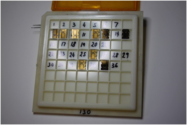
After the sensing devices are diced and separated, they are stored in device storage containers with row and column locations corresponding to those on the processed wafers as shown below.
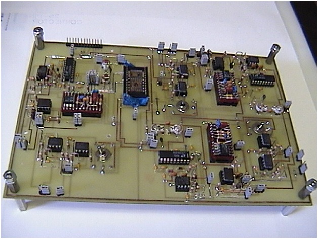
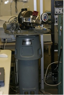
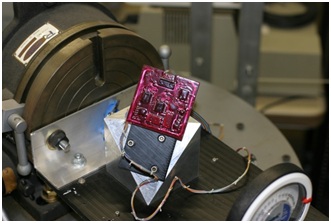
Depending upon the type of testing required, special fixtures are fabricated. Special connectors with pogo pins are usually employed to make temporary contact with the sensor pads designed for electrical interface. Some sensors can be electrically or otherwise stimulated to observe and measure physical movements under a microscope. Special electronics fixtures are designed for exciting the sensing element and measurements, usually interfaced with a data collecting laptop. The above phtograph shows a Testing Fixture for Rotary Gyro and accel combo device.
Each sensor is married to its own electronics (for example the electronics for a servo loop ). A cluster of these devices is enclosed in a box (for example an IMU). Finally, a micro processor with proper memory and I/O functions is used to form a system. The system, thus formed, is tested with a spectrum of inputs under different environmental conditions for calibration and comparison to a standard known reference. The reference could a simulated electronics box controlled by a computer. Response time for stable output is determined. Turn-on-to-turn-on variability is measured. A good example of system level testing is the Rate Table testing of IMUs and Inertial Navigation Systems. For rate table testing, the test electronics is divided into two partitions. One part moves along with the system on the table, and the other part is kept off table. The rate table has multiple slip rings for signals and power interfacing between the two partitions.